Bus
Source: GridKit/Model/PowerFlow/Bus/README.md
Bus Model
A bus is a point of interconnection of electrical devices. Each bus \(i\) has four quantities associated with it: net real power (\(P_{i}\)), net reactive power (\(Q_{i}\)), bus voltage magnitude (\(\vert\)\(V_{i}\)\(\vert\)), and bus voltage angle (\(\theta _{i}\)). For the power flow, for each bus, two quantities are specified as input data and two variables are unknown. Depending on the available input data, there are three types of buses in the power system model: PQ (load) bus, PV (generator) bus, and a Slack (swing/reference) bus, where the following applies:
Load bus - \(P\) and \(Q\) are defined
Generator bus - \(P\) and \(\vert\)\(V\)\(\vert\) are defined
Slack bus - \(\vert\)\(V\)\(\vert\) and \(\theta\) are defined
Type of the bus is determined based on the available input data that in return depends on what devices are attached to the bus.
PQ Bus Most of the buses in the power system are modeled as PQ buses. Those buses do not have voltage control devices such as a generator or switched shunts and are not remotely controlled by any generator.
PV Bus PV buses have some sort of controllable reactive power resource in order to maintain the voltage magnitude (voltage setpoint). Besides \(P\) and \(\vert\)\(V\)\(\vert\) values, \(Q_{Gimax}\) and \(Q_{Gimin}\) are part of the input data set as well. During the power flow solution process, PV bus can become PQ bus in the case when generator (or switched shunt) that is regulating the voltage hits the max or min \(Q_{G}\) limits, thus it cannot longer regulate the voltage.
Slack Bus For the power system studies, only one bus is designated to be a slack bus per electrical island. The slack bus does not exist in the actual power system but it is required for solving the power flow. The location of the slack bus influences the complexity of the calculations and usually is selected to be a bus with a large dispatchable generator. The slack bus angle is set to reference value or zero degrees and all other bus angles are expressed using the slack bus voltage phasor as their reference.
Sign Convention There exist two:
Load convention: current enters positive terminal of the circuit element, and if P(Q) is positive that means power is absorbed, or if negative then it is delivered.
Generator convention: current leaves positive terminal of the circuit element, and if P(Q) is positive that means power is delivered, or if negative then it is absorbed.
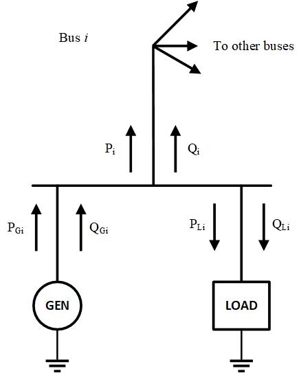
Figure 1: Sign convention for the power flow at the bus \(i\)
Using the previously defined sign convention, real and reactive power delivered to bus \(i\) are then defined as follows:
Other Parameters Buses are uniquely defined by their ID (number or name). Besides, each bus should have associated Nominal Voltage value.