SynchronousMachine
Source: GridKit/Model/PhasorDynamics/SynchronousMachine/README.md
General Synchronous Machine Model
Convention
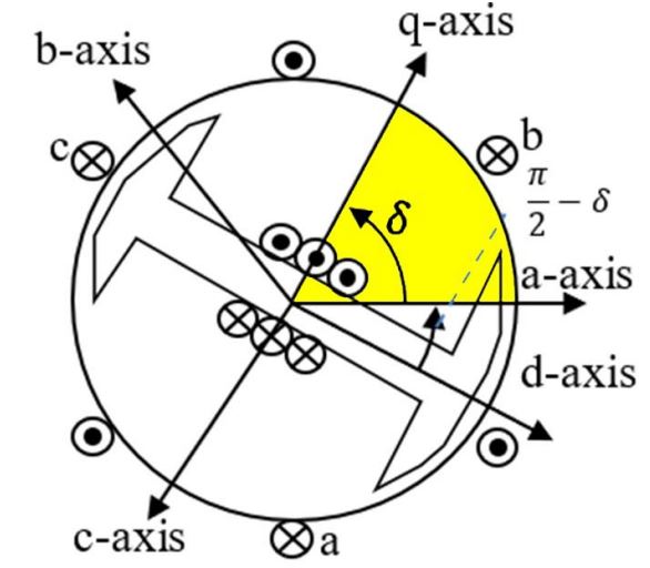
Figure 1: Synchronous Machine. Figure courtesy of PowerWorld
The following conventions are used for the d-q reference frame.
The q-axis leads the d-axis
The Rotor angle is w.r.t. to q-axis
Types
Classical Generator (See GenClassical)
Round Rotor (See GENROU)
Salient Rotor/Pole (See GENSAL)
GENPWS
GENTPF
GENTPJ
GENQEC
Per-Unit Basis
In relevant models, the terminal impedances are on the generator impedance base. To convert to the network base, the following must be performed.
For example, say the terminal impedence is \(Z=0.05\) in per-unit on the machine’s base of \(S_{base,machine}=50\) MW, and the system base is \(S_{base,sys}=100\) MW. Then the terminal impedance on the system base is calculated as follows.
Saturation
Saturation means increasingly large amounts of current are needed to increase the flux density. The Scaled Quadratic saturation model is currently implemented.