PSS1A
Source: GridKit/Model/PhasorDynamics/Stabilizer/PSS1A/README.md
[!NOTE] This is not yet implemented
[!NOTE] The Parameters, variables, and equations need to be formatted and verified - this is WIP.
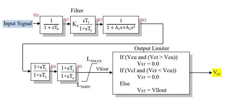
Figure 1: Power system stabilizer PSS1A model. Figure courtesy of PowerWorld
Model Parameters
\(I_{cs}\) - stabilizer input code, (2)
\(A_{1}\) - notch filter parameters, (0)
\(A_{2}\) - notch filter parameters, (0)
\(T_{1}\) - lead/lag time constant, sec (0.25)
\(T_{2}\) - lead/lag time constant, sec (0.03)
\(T_{3}\) - lead/lag time constant, sec (0.25)
\(T_{4}\) - lead/lag time constant, sec (0.03)
\(T_{5}\) - washout numerator time constant, sec (20)
\(T_{6}\) - washout denomirator time constant/transducer time constant, sec (0.02)
\(K_{S}\) - stabilizer gains, (10)
\(L_{smax}\) - maximum stabilizer output, pu (0.1)
\(L_{smin}\) - minimum stabilizer output, pu (-0.1)
\(V_{cu}\) - stabilizer input cutoff threshold, pu (0)
\(V_{cl}\) - stabilizer input cutoff threshold, pu (0)
Model Variables
These were the variables listed in the old documentation.
rotor speed deviation (p.u.)
bus frequency deviation (p.u.) - default
generator electrical power in Gen MVA Base (p.u.)
generator accelerating power (p.u.)
bus voltage (p.u.)
derivative of p.u. bus voltage
Internal Variables
Differential
TBD
Algebraic
TBD
External Variables
Differential
None.
Algebraic
Symbol |
Units |
Description |
Note |
|---|---|---|---|
\(u\) |
[p.u.] |
Stabilizer input signal |
|
\(V_{ct}\) |
[p.u.] |
Cutout signal (compared to \(V_{cl},V_{cu}\)) |
from the block diagram |