GENSALwS
Source: GridKit/Model/PhasorDynamics/SynchronousMachine/GENSALwS/README.md
GENSAL
This synchronous machine model is 5th order and is specifically designed for salient-pole machines. It is a standard model used in phasor-domain industry stability studies. See the General Synchronous Machine Model for general synchronous machine information.
Notes:
\(X_q''=X_d''\) (no subtransient saliency)
\(X_q=X_q'\)
\(T'_{q0}\) is neglected
Only d-axis affected by saturation
Block Diagram
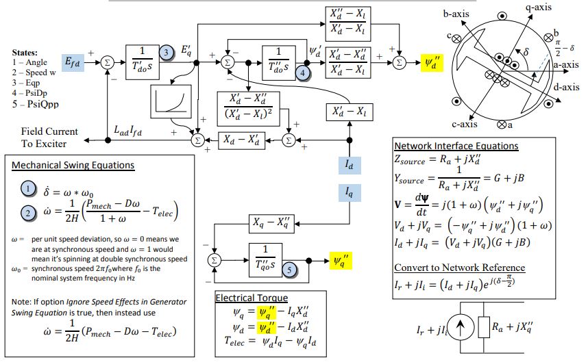
Figure 2: GENSAL. Figure courtesy of PowerWorld
Model Parameters
Symbol |
Units |
Description |
Typical Value |
Note |
|---|---|---|---|---|
\(P_0\) |
[p.u.] |
Initial active power injection |
1.0 |
|
\(Q_0\) |
[p.u.] |
Initial reactive power injection |
0.0 |
|
\(H\) |
[s] |
rotor inertia |
3 |
|
\(D\) |
[p.u.] |
damping coefficient |
0 |
|
\(R_a\) |
[p.u.] |
winding resistance |
0 |
|
\(T'_{d0}\) |
[s] |
Open circuit direct axis transient time const. |
7 |
|
\(T''_{d0}\) |
[s] |
Open circuit direct axis sub-transient time const. |
0.04 |
|
\(T''_{q0}\) |
[s] |
Open circuit quadrature axis sub-transient time const. |
0.05 |
|
\(X_d\) |
[p.u.] |
Direct axis synchronous reactance |
2.1 |
|
\(X'_d\) |
[p.u.] |
Direct axis transient reactance |
0.2 |
|
\(X''_d\) |
[p.u.] |
Direct axis sub-transient reactance |
0.18 |
|
\(X_q\) |
[p.u.] |
Quadrature axis synchronous reactance |
0.5 |
|
\(X_{\ell}\) |
[p.u.] |
Stator leakage reactance |
0.15 |
|
\(S_{10}\) |
[p.u.] |
Saturation factor at 1.0 pu flux |
0 |
|
\(S_{12}\) |
[p.u.] |
Saturation factor at 1.2 pu flux |
0 |
|
\(S_\mathrm{mach}\) |
[MVA] |
Machine power base |
100 |
Model Derived Parameters
System bases are taken from the system at initialization.
Model Variables
Internal Variables
Differential
Symbol |
Units |
Description |
Note |
|---|---|---|---|
\(\delta\) |
[rad] |
Machine internal rotor angle |
|
\(\omega\) |
[p.u.] |
Machine speed deviation |
Optionally read by governor or stabilizer component |
\(E'_q\) |
[p.u.] |
Quadrature axis transient flux |
|
\(\psi'_d\) |
[p.u.] |
Direct axis transient flux |
|
\(\psi''_q\) |
[p.u.] |
Total q-axis subtransient flux |
Algebraic
Symbol |
Units |
Description |
Note |
|---|---|---|---|
\(\psi''_d\) |
[p.u.] |
Total d-axis subtransient flux |
|
\(k_{sat}\) |
[p.u.] |
Additive saturation signal |
|
\(V_d\) |
[p.u.] |
Machine internal voltage, d-axis |
|
\(V_q\) |
[p.u.] |
Machine internal voltage, q-axis |
|
\(T_e\) |
[p.u.] |
Electrical torque |
|
\(I_d\) |
[p.u.] |
Terminal current, d-axis |
|
\(I_q\) |
[p.u.] |
Terminal current, q-axis |
|
\(I_r\) |
[p.u.] |
Terminal current, real component on network reference frame |
Read by bus and optionally by controllers |
\(I_i\) |
[p.u.] |
Terminal current, imaginary component on network reference frame |
Read by bus and optionally by controllers |
External Variables
Differential
None.
Algebraic
Symbol |
Units |
Description |
Note |
|---|---|---|---|
\(V_r\) |
[p.u.] |
Terminal voltage, real component on network reference frame |
owned by bus object |
\(V_i\) |
[p.u.] |
Terminal voltage, imaginary component on network reference frame |
owned by bus object |
\(P_m\) |
[p.u.] |
Mechanical power from the prime mover |
Owned by governor, constant if no governor is connected to the machine |
\(E_{fd}\) |
[p.u.] |
Field winding voltage from the excitation system |
Owned by exciter, constant if no exciter is connected to the machine |
Model Equations
Differential Equations
Algebraic Equations
Initialization
Using the power-flow solution, initial currents are calculated from active and reactive power injection. The remaining variables are initialized from the steady-state GENSAL equations.
Model Outputs
Symbol |
Units |
Description |
Note |
|---|---|---|---|
\(I_r\) |
[p.u.] |
Terminal current, real component on network reference frame |
Oriented leaving the machine, system base |
\(I_i\) |
[p.u.] |
Terminal current, imaginary component on network reference frame |
Oriented leaving the machine, system base |
\(P\) |
[p.u.] |
Active power, \(V_rI_r+V_iI_i\) |
Oriented leaving the machine, system base |
\(Q\) |
[p.u.] |
Reactive power, \(V_iI_r-V_rI_i\) |
Oriented leaving the machine, system base |
\(\delta\) |
[rad] |
Machine internal rotor angle |
|
\(\omega\) |
[p.u.] |
Machine speed deviation |
\(\omega=0\) at synchronous speed |
\(\text{speed}\) |
[p.u.] |
Per-unit machine speed |
\(1+\omega\) |
\(E'_q\) |
[p.u.] |
Quadrature axis transient flux |
Machine base |
\(\psi'_d\) |
[p.u.] |
Direct axis transient flux |
Machine base |
\(\psi''_q\) |
[p.u.] |
Total q-axis subtransient flux |
Machine base |
\(\psi''_d\) |
[p.u.] |
Total d-axis subtransient flux |
Machine base |
\(V_d\) |
[p.u.] |
Machine internal voltage, d-axis |
Machine base |
\(V_q\) |
[p.u.] |
Machine internal voltage, q-axis |
Machine base |
\(T_e\) |
[p.u.] |
Electrical torque |
Machine base |
\(I_d\) |
[p.u.] |
Terminal current, d-axis |
Machine base |
\(I_q\) |
[p.u.] |
Terminal current, q-axis |
Machine base |