IEEEG1
Source: GridKit/Model/PhasorDynamics/Governor/IEEEG1/README.md
IEEE Type 1 Speed-Governor Model (IEEEG1)
IEEEG1 is a steam turbine-governor model with speed deadband, a governor lead-lag, rate- and position-limited governor output, optional nonlinear governor gain, turbine bowl and reheat stages, and separate high-pressure and low-pressure mechanical-power outputs.
Notes:
Input and output powers are on the turbine-rating base when
Trate > 0; otherwise the connected machine MVA base is used.The dashed
dbL/dbHspeed deadband block is only for IEEEG1D. IEEEG1 uses the Type 1 no-offsetdb1block documented with CommonMathdeadband1.Source governor-response settings may modify \(U_o\), \(U_c\), \(P^{\max}\), and \(P^{\min}\) before the equations are evaluated.
PSSE IEEEG1 source data may omit
db1,db2, nonlinear-gain points, and turbine rating; those omitted features must be documented as inactive rather than silently dropped.
Block Diagram
Standard model of the IEEEG1 Governor.
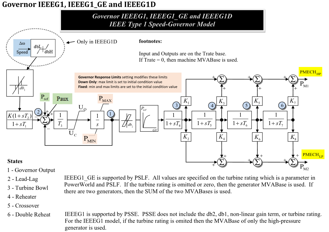
Figure 1: Governor IEEEG1 model. Figure courtesy of PowerWorld
Model Parameters
Symbol |
Units |
JSON |
Description |
Typical Value |
Note |
|---|---|---|---|---|---|
\(K\) |
[p.u.] |
|
Governor speed-control gain |
20.0 |
Block name: |
\(T_1\) |
[sec] |
|
Governor lead-lag denominator time constant |
0.0 |
Block name: |
\(T_2\) |
[sec] |
|
Governor lead-lag numerator time constant |
0.0 |
Block name: |
\(T_3\) |
[sec] |
|
Governor output servo time constant |
0.1 |
Block name: |
\(U_o\) |
[p.u./s] |
|
Maximum opening rate |
0.1 |
Source label: |
\(U_c\) |
[p.u./s] |
|
Maximum closing rate |
-0.1 |
Source label: |
\(P^{\max}\) |
[p.u.] |
|
Maximum governor output |
1.0 |
Block name: |
\(P^{\min}\) |
[p.u.] |
|
Minimum governor output |
0.0 |
Block name: |
\(T_4\) |
[sec] |
|
Turbine bowl time constant |
0.3 |
State 3 in Fig. 1 |
\(K_1\) |
[p.u.] |
|
High-pressure fraction from turbine bowl |
0.2 |
Top output branch |
\(K_2\) |
[p.u.] |
|
Low-pressure fraction from turbine bowl |
0.0 |
Bottom output branch |
\(T_5\) |
[sec] |
|
Reheater time constant |
5.0 |
State 4 in Fig. 1 |
\(K_3\) |
[p.u.] |
|
High-pressure fraction from reheater |
0.3 |
Top output branch |
\(K_4\) |
[p.u.] |
|
Low-pressure fraction from reheater |
0.0 |
Bottom output branch |
\(T_6\) |
[sec] |
|
Crossover time constant |
0.5 |
State 5 in Fig. 1 |
\(K_5\) |
[p.u.] |
|
High-pressure fraction from crossover |
0.5 |
Top output branch |
\(K_6\) |
[p.u.] |
|
Low-pressure fraction from crossover |
0.0 |
Bottom output branch |
\(T_7\) |
[sec] |
|
Double-reheat time constant |
0.5 |
State 6 in Fig. 1 |
\(K_7\) |
[p.u.] |
|
High-pressure fraction from double reheat |
0.0 |
Top output branch |
\(K_8\) |
[p.u.] |
|
Low-pressure fraction from double reheat |
0.0 |
Bottom output branch |
\(D_{\omega}\) |
[p.u.] |
|
Type 1 speed deadband threshold |
0.0 |
Block name: |
\(\epsilon\) |
[p.u.] |
|
Nonlinear gain smoothing/curve tolerance |
0.0 |
Source nonlinear gain setting |
\(D_{\mathrm{gv}}\) |
[p.u.] |
|
Governor-output backlash/deadband width |
0.0 |
Block name: |
\(P^{\mathrm{rate}}\) |
[MW] |
|
Optional turbine-rating power base |
0.0 |
|
The optional nonlinear governor gain curve is represented by source points:
Symbol |
Units |
JSON |
Description |
Typical Value |
Note |
|---|---|---|---|---|---|
\(G_V^{(k)}\) |
[p.u.] |
|
Governor-output curve input point \(k\) |
0.0 |
Source labels: |
\(P_{\mathrm{GV}}^{(k)}\) |
[p.u.] |
|
Governor-output curve value point \(k\) |
0.0 |
Source labels: |
Parameter Validation
Invalid IEEEG1 parameter sets are rejected by the following checks. If source governor-response settings adjust limits, apply these checks to the effective values used by the equations.
Model Derived Parameters
The governor component base and nonlinear governor-output curve are:
CommonMath defines the linear segment helper used by \(N_{\mathrm{GV}}\).
Model Variables
Internal Variables
Differential
Symbol |
Units |
Description |
Note |
|---|---|---|---|
\(P_{\mathrm{GV}}\) |
[p.u.] |
Governor output |
State 1 in Fig. 1 |
\(x_{\mathrm{ll}}\) |
[p.u.] |
Governor lead-lag state |
State 2 in Fig. 1 |
\(x_4\) |
[p.u.] |
Turbine bowl state |
State 3 in Fig. 1; denominator \(T_4\) |
\(x_5\) |
[p.u.] |
Reheater state |
State 4 in Fig. 1; denominator \(T_5\) |
\(x_6\) |
[p.u.] |
Crossover state |
State 5 in Fig. 1; denominator \(T_6\) |
\(x_7\) |
[p.u.] |
Double-reheat state |
State 6 in Fig. 1; denominator \(T_7\) |
Algebraic
Symbol |
Units |
Description |
Note |
|---|---|---|---|
\(\omega_{\mathrm{db}}\) |
[p.u.] |
Deadbanded speed deviation |
Defined by CommonMath |
\(y_{\omega}\) |
[p.u.] |
Lead-lag-conditioned speed signal |
Output of \(K(1+sT_2)/(1+sT_1)\) |
\(e_G\) |
[p.u.] |
Governor command error |
Sum of references minus speed and output feedback |
\(r_G\) |
[p.u./s] |
Rate-limited governor derivative target |
Limited by \(U_c\) and \(U_o\) |
\(P_{\mathrm{GV}}^{\mathrm{nl}}\) |
[p.u.] |
Nonlinear governor gain output |
Output of |
\(P_m^{\mathrm{HP}}\) |
[p.u.] |
High-pressure mechanical-power output |
Source label: |
\(P_m^{\mathrm{LP}}\) |
[p.u.] |
Low-pressure mechanical-power output |
Source label: |
External Variables
Differential
None.
Algebraic
Symbol |
Units |
Description |
Note |
|---|---|---|---|
\(\omega\) |
[p.u.] |
Machine speed deviation |
Source label: |
\(P_{\mathrm{ref}}\) |
[p.u.] |
Governor reference |
Source label: |
\(P_{\mathrm{aux}}\) |
[p.u.] |
Auxiliary power input |
Source label: |
Model Equations
Differential Equations
CommonMath defines the Anti-Windup target and smooth approximation.
Algebraic Equations
CommonMath defines helper targets and smooth approximations for deadband1, deadband2, clamp, and linseg. When \(T_1=T_2=0\), the governor lead-lag block is bypassed so \(y_{\omega}=K\omega_{\mathrm{db}}\).
Initialization
Initialization is performed by evaluating the steady-state residuals in dependency order. Let subscript \(0\) denote initial values and set all internal derivatives to zero. For a standard power-flow start:
Given initialized high- and low-pressure mechanical powers, solve the turbine chain by choosing \(P_{\mathrm{GV},0}\) so that the turbine fractions reproduce the connected machine operating point:
This closed-form start requires the effective governor output to lie inside \(P^{\min}\) and \(P^{\max}\) and the opening/closing rate limits to be inactive. Starts where governor response limits fix the limits to the initial condition must document those effective limits before applying the residuals.
Model Outputs
Output |
Units |
Description |
Note |
|---|---|---|---|
|
[p.u.] |
High-pressure mechanical-power output |
\(P_m^{\mathrm{HP}}\) |
|
[p.u.] |
Low-pressure mechanical-power output |
\(P_m^{\mathrm{LP}}\) |
|
[p.u.] |
Governor output |
State 1 |
|
[p.u.] |
Governor lead-lag state |
State 2 |
|
[p.u.] |
Turbine bowl state |
State 3 |
|
[p.u.] |
Reheater state |
State 4 |
|
[p.u.] |
Crossover state |
State 5 |
|
[p.u.] |
Double-reheat state |
State 6 |