IEEEST
Source: GridKit/Model/PhasorDynamics/Stabilizer/IEEEST/README.md
IEEE Stabilizer Model (IEEEST)
Standard IEEE power system stabilizer: 4th-order notch filter, two lead–lag blocks, washout, and output limiter.
Block Diagram
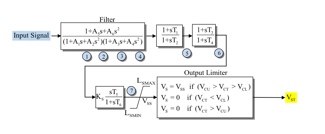
Figure 1: Stabilizer IEEEST model. Figure courtesy of PowerWorld
Model Parameters
Symbol |
Units |
Description |
Typical Value |
|---|---|---|---|
\(A_1\) |
[s] |
Notch denominator coefficient |
1.013 |
\(A_2\) |
[s²] |
Notch denominator coefficient |
0.013 |
\(A_3\) |
[s] |
Notch denominator coefficient |
0.0 |
\(A_4\) |
[s²] |
Notch denominator coefficient |
0.0 |
\(A_5\) |
[s] |
Notch numerator coefficient |
1.013 |
\(A_6\) |
[s²] |
Notch numerator coefficient |
0.113 |
\(T_1\) |
[s] |
Lead–lag 1 numerator time constant |
0.0 |
\(T_2\) |
[s] |
Lead–lag 1 denominator time constant |
0.02 |
\(T_3\) |
[s] |
Lead–lag 2 numerator time constant |
0.0 |
\(T_4\) |
[s] |
Lead–lag 2 denominator time constant |
0.0 |
\(T_5\) |
[s] |
Washout numerator time constant |
1.65 |
\(T_6\) |
[s] |
Washout denominator time constant |
1.65 |
\(K_s\) |
[p.u.] |
Stabilizer gain |
3.0 |
\(L_s^{\min}\) |
[p.u.] |
Minimum stabilizer output limit |
-0.1 |
\(L_s^{\max}\) |
[p.u.] |
Maximum stabilizer output limit |
0.1 |
The IEEE 421.5 IEEEST also defines a cutout window (\(V_{cl}\), \(V_{cu}\)) and an input delay (\(T_{delay}\)). These parameters are accepted for input-format compatibility but are not modeled here.
Derived Parameters
Model Variables
Internal Variables
Differential
Symbol |
Units |
Description |
|---|---|---|
\(x_1, x_2, x_3, x_4\) |
[-] |
Notch filter states |
\(x_5\) |
[-] |
Lead–lag 1 state |
\(x_6\) |
[-] |
Lead–lag 2 state |
\(x_7\) |
[-] |
Washout state |
Algebraic
Symbol |
Units |
Description |
|---|---|---|
\(v_4\) |
[p.u.] |
Notch filter output |
\(v_5\) |
[p.u.] |
Lead–lag 1 output |
\(v_6\) |
[p.u.] |
Lead–lag 2 output |
\(v_7\) |
[p.u.] |
Unlimited stabilizer signal |
\(V_{ss}\) |
[p.u.] |
Limited stabilizer signal (model output) |
External Variables
Algebraic
Symbol |
Units |
Description |
|---|---|---|
\(u\) |
[p.u.] |
Stabilizer input signal |
Model Equations
Differential Equations
Algebraic Equations
The output limiter uses GridKit’s smooth Clamp.
Initialization
All states and their derivatives initialize to zero. The stabilizer comes online at rest and produces signal only in response to deviations in the input \(u\).