ESDC2A
Source: GridKit/Model/PhasorDynamics/Exciter/ESDC2A/README.md
IEEE Type DC2A Excitation System Model (ESDC2A)
ESDC2A is an IEEE Type DC excitation system with a voltage transducer, lead-lag input compensation, high-value under-excitation limiter selection, limited voltage regulator, exciter feedback, saturation, and optional speed multiplier.
Notes:
Internal voltage signals are on model base unless otherwise stated.
The diagram labels the optional multiplier input as
Speed; GridKit uses machine speed deviation, so the enabled multiplier is \(1+\omega\).The PowerWorld selector
UELroutes \(V_{\mathrm{uel}}\) through the summing junction whenUEL >= 2, and through the high-value gate whenUEL < 2.The
exclimflag lower-limits the exciter feedback signal at zero when nonzero; otherwise the feedback signal is unlimited.
Block Diagram
Standard model of the ESDC2A Exciter.
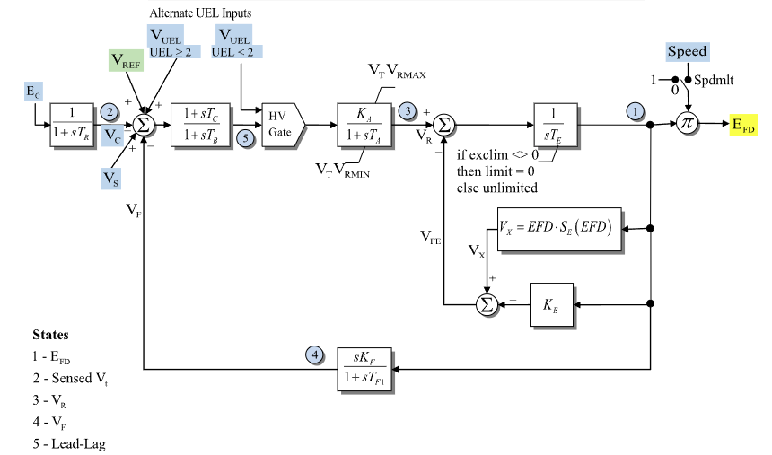
Figure 1: Exciter ESDC2A model. Figure courtesy of PowerWorld
Model Parameters
Symbol |
Units |
JSON |
Description |
Typical Value |
Note |
|---|---|---|---|---|---|
\(T_R\) |
[sec] |
|
Transducer time constant |
0.0 |
Block name: |
\(K_A\) |
[p.u.] |
|
Voltage-regulator gain |
40.0 |
Block name: |
\(T_A\) |
[sec] |
|
Voltage-regulator time constant |
0.1 |
Block name: |
\(T_B\) |
[sec] |
|
Lag time constant for voltage-regulator input lead-lag |
0.0 |
Block name: |
\(T_C\) |
[sec] |
|
Lead time constant for voltage-regulator input lead-lag |
0.0 |
Block name: |
\(V_R^{\max}\) |
[p.u.] |
|
Maximum voltage-regulator output |
1.0 |
Block name: |
\(V_R^{\min}\) |
[p.u.] |
|
Minimum voltage-regulator output |
-1.0 |
Block name: |
\(K_E\) |
[p.u.] |
|
Exciter field-resistance line-slope margin |
0.1 |
Block name: |
\(T_E\) |
[sec] |
|
Exciter time constant |
0.5 |
Block name: |
\(K_F\) |
[p.u.] |
|
Stabilizing feedback gain |
0.05 |
Block name: |
\(T_{F1}\) |
[sec] |
|
Feedback lead time constant |
0.7 |
Block name: |
\(s_{\mathrm{spd}}\) |
[binary] |
|
Speed multiplier flag |
0 |
Block name: |
\(E_1\) |
[p.u.] |
|
First saturation voltage point |
2.8 |
Block name: |
\(S_E(E_1)\) |
[p.u.] |
|
Saturation value at \(E_1\) |
0.08 |
Block name: |
\(E_2\) |
[p.u.] |
|
Second saturation voltage point |
3.7 |
Block name: |
\(S_E(E_2)\) |
[p.u.] |
|
Saturation value at \(E_2\) |
0.33 |
Block name: |
\(I_{\mathrm{uel}}\) |
[integer] |
|
Under-excitation limiter input-location selector |
0 |
Block name: |
\(s_{\mathrm{lim}}\) |
[binary] |
|
Exciter feedback lower-limit flag |
1 |
Block name: |
Parameter Validation
Invalid ESDC2A parameter sets are rejected by the following checks. Source data may apply PowerWorld-style autocorrections before these equations are evaluated.
The saturation points are either disabled together,
or define a valid two-point quadratic saturation fit:
Model Derived Parameters
The UEL routing flag and off-mode flag complements are:
The saturation curve is fitted from the two supplied saturation points. If both saturation factors are zero, use \(S_A=0\) and \(S_B=0\). Otherwise:
Model Variables
Internal Variables
Differential
Symbol |
Units |
Description |
Note |
|---|---|---|---|
\(E_{\mathrm{fd}}'\) |
[p.u.] |
Field-voltage state before optional speed multiplier |
State 1 in Fig. 1; source label: |
\(V_C\) |
[p.u.] |
Sensed compensated voltage |
State 2 in Fig. 1; source label: |
\(V_R\) |
[p.u.] |
Voltage-regulator output |
State 3 in Fig. 1; source label: |
\(V_F\) |
[p.u.] |
Stabilizing feedback washout output |
State 4 in Fig. 1; source label: |
\(x_{\mathrm{ll}}\) |
[p.u.] |
Lead-lag block state |
State 5 in Fig. 1; source label: |
Algebraic
Symbol |
Units |
Description |
Note |
|---|---|---|---|
\(e_V\) |
[p.u.] |
Voltage-regulator input error before lead-lag block |
Includes selected \(V_{\mathrm{uel}}\) summing-junction input |
\(V_{\mathrm{ll}}\) |
[p.u.] |
Lead-lag block output |
Input to high-value gate |
\(V_{\mathrm{hv}}\) |
[p.u.] |
High-value gate output |
Selects \(V_{\mathrm{ll}}\) or alternate \(V_{\mathrm{uel}}\) |
\(S_E\) |
[p.u.] |
Saturation coefficient evaluated at \(E_{\mathrm{fd}}'\) |
Uses derived saturation curve |
\(V_{\mathrm{fe}}\) |
[p.u.] |
Exciter feedback signal after optional lower limit |
Lower limited at zero when \(s_{\mathrm{lim}}=1\) |
\(E_{\mathrm{fd}}\) |
[p.u.] |
Field-voltage output |
Output after optional speed multiplier |
External Variables
Differential
None.
Algebraic
Symbol |
Units |
Description |
Note |
|---|---|---|---|
\(E_C\) |
[p.u.] |
Compensated terminal voltage magnitude |
Source label: |
\(V_{\mathrm{ref}}\) |
[p.u.] |
Voltage-control reference |
Source label: |
\(V_S\) |
[p.u.] |
Stabilizer input signal |
Source label: |
\(V_{\mathrm{uel}}\) |
[p.u.] |
Under-excitation limiter input |
Source label: |
\(\omega\) |
[p.u.] |
Machine speed deviation |
Source label: |
Model Equations
Differential Equations
CommonMath defines the Anti-Windup target and smooth approximation.
Algebraic Equations
CommonMath defines the helper targets and smooth approximations for max and the primitives ramp and quadratic ramp \(\rho\) and \(q\). When \(T_B=T_C=0\), the lead-lag block is bypassed so \(V_{\mathrm{ll}}=e_V\).
Initialization
The machine initializes \(E_{\mathrm{fd}}\) first. For a standard unsaturated start, ESDC2A reads that value along with attached \(\omega\), \(E_C\), \(V_S\), and \(V_{\mathrm{uel}}\), sets all internal derivatives to zero, and evaluates:
This closed-form start requires \(1 + s_{\mathrm{spd}}\omega_0 \ne 0\), \(V_R^{\min} \le V_{R,0} \le V_R^{\max}\), and, when \(s_{\mathrm{uel}}=0\), \(V_{\mathrm{hv},0} \ge V_{\mathrm{uel},0}\). Saturated voltage-regulator starts and active high-value-gate starts are outside these closed-form equations.
Model Outputs
Output |
Units |
Description |
Note |
|---|---|---|---|
|
[p.u.] |
Field-voltage output |
\(E_{\mathrm{fd}}\) |
|
[p.u.] |
Sensed compensated voltage |
\(V_C\) |
|
[p.u.] |
Voltage-regulator output |
\(V_R\) |
|
[p.u.] |
Stabilizing feedback state |
\(V_F\) |
|
[p.u.] |
Saturation coefficient |
\(S_E\) |
|
[p.u.] |
Exciter feedback signal |
\(V_{\mathrm{fe}}\) |