GGOV1
Source: GridKit/Model/PhasorDynamics/Governor/GGOV1/README.md
GE General Governor-Turbine Model (GGOV1)
GGOV1 is a general governor-turbine model with electrical-power measurement, speed/load reference selection, proportional/integral/derivative governor control, load limiting, acceleration limiting, temperature limiting, actuator rate limits, turbine lag/lead dynamics, and optional diesel damping.
Notes:
Internal control, valve-stroke, and turbine-power quantities are on the GGOV1 component base unless otherwise stated.
The dashed speed deadband block and
Dbsource field are only for GGOV1D. GGOV1 uses the speed input directly.Source governor-response settings may modify \(V^{\max}\) and \(V^{\min}\) before the equations are evaluated.
The source diagram notes that
RupandRdowninputs are not implemented in Simulator; the equations below do not use those source fields.
Block Diagram
Standard model of the GGOV1 Governor.
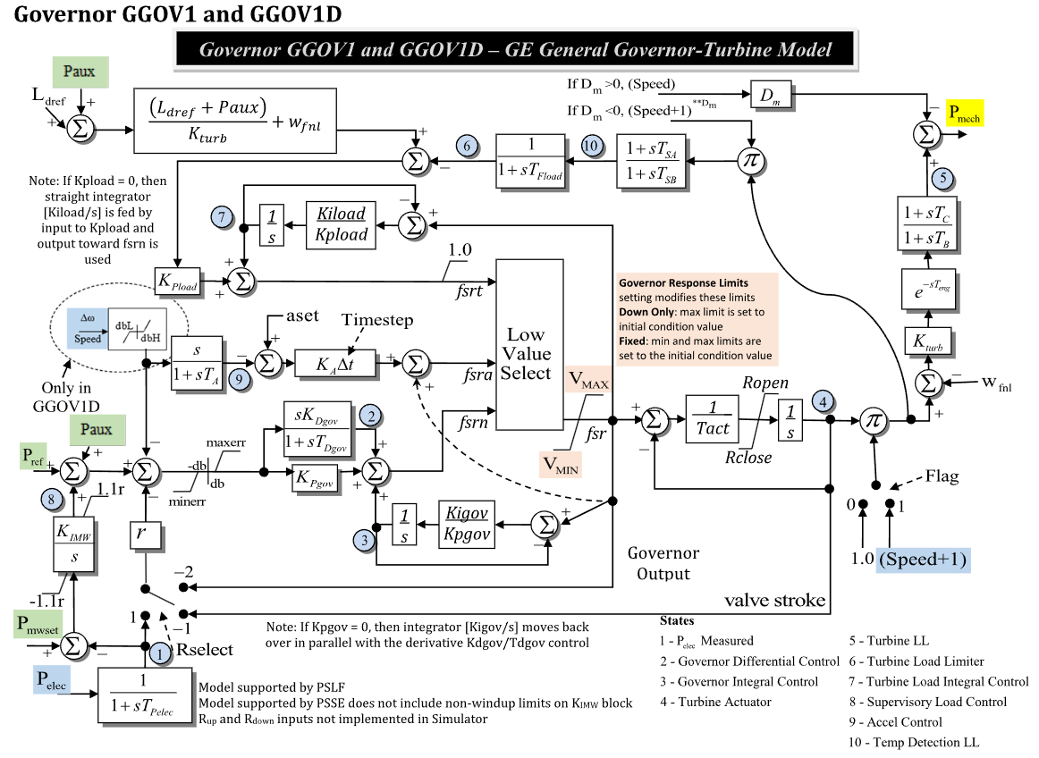
Figure 1: Governor GGOV1 model. Figure courtesy of PowerWorld
Model Parameters
Symbol |
Units |
JSON |
Description |
Typical Value |
Note |
|---|---|---|---|---|---|
\(P^{\mathrm{rate}}\) |
[MW] |
|
Optional turbine-rating power base |
0.0 |
|
\(I_R\) |
[integer] |
|
Droop feedback selector |
1 |
Source label: |
\(s_\mathrm{flag}\) |
[binary] |
|
Turbine-speed multiplier selector |
1 |
1 uses \(1+\omega\), 0 uses 1.0 |
\(R\) |
[p.u.] |
|
Permanent droop |
0.05 |
Source label: |
\(T_\mathrm{pelec}\) |
[sec] |
|
Electrical-power measurement time constant |
0.0 |
State 1 in Fig. 1 |
\(e^{\max}\) |
[p.u.] |
|
Maximum governor error |
1.0 |
Source label: |
\(e^{\min}\) |
[p.u.] |
|
Minimum governor error |
-1.0 |
Source label: |
\(K_\mathrm{pgov}\) |
[p.u.] |
|
Governor proportional gain |
10.0 |
Block name: |
\(K_\mathrm{igov}\) |
[p.u./s] |
|
Governor integral gain |
1.0 |
Block name: |
\(K_\mathrm{dgov}\) |
[p.u.] |
|
Governor differential gain |
0.0 |
Block name: |
\(T_\mathrm{dgov}\) |
[sec] |
|
Governor differential time constant |
0.0 |
Block name: |
\(V^{\max}\) |
[p.u.] |
|
Maximum governor output before actuator |
1.0 |
Governor response limits may adjust this value |
\(V^{\min}\) |
[p.u.] |
|
Minimum governor output before actuator |
0.0 |
Governor response limits may adjust this value |
\(T_\mathrm{act}\) |
[sec] |
|
Turbine actuator time constant |
0.1 |
State 4 in Fig. 1 |
\(R_\mathrm{open}\) |
[p.u./s] |
|
Maximum actuator opening rate |
1.0 |
Source label: |
\(R_\mathrm{close}\) |
[p.u./s] |
|
Maximum actuator closing rate |
-1.0 |
Source label: |
\(K_\mathrm{turb}\) |
[p.u.] |
|
Turbine gain |
1.0 |
Block name: |
\(W_\mathrm{fnl}\) |
[p.u.] |
|
No-load fuel flow |
0.0 |
Source label: |
\(T_B\) |
[sec] |
|
Turbine lead-lag denominator time constant |
0.0 |
State 5 in Fig. 1 |
\(T_C\) |
[sec] |
|
Turbine lead-lag numerator time constant |
0.0 |
Block name: |
\(T_\mathrm{eng}\) |
[sec] |
|
Engine transport lag |
0.0 |
Source label: |
\(T_\mathrm{fload}\) |
[sec] |
|
Load-limiter lag time constant |
0.0 |
State 6 in Fig. 1 |
\(K_\mathrm{pload}\) |
[p.u.] |
|
Load-limiter proportional gain |
0.0 |
Block name: |
\(K_\mathrm{iload}\) |
[p.u./s] |
|
Load-limiter integral gain |
0.0 |
State 7 in Fig. 1 |
\(L_\mathrm{dref}\) |
[p.u.] |
|
Load reference |
1.0 |
Source label: |
\(D_m\) |
[p.u.] |
|
Diesel damping gain |
0.0 |
Source label: |
\(K_\mathrm{imw}\) |
[p.u./s] |
|
Supervisory load-control integral gain |
0.0 |
State 8 in Fig. 1 |
\(A_\mathrm{set}\) |
[p.u.] |
|
Acceleration-control reference |
0.0 |
Source label: |
\(K_A\) |
[p.u.] |
|
Acceleration-control gain |
0.0 |
Block name: |
\(T_A\) |
[sec] |
|
Acceleration-control time constant |
0.0 |
State 9 in Fig. 1 |
\(T_\mathrm{sa}\) |
[sec] |
|
Temperature-detection numerator time constant |
0.0 |
State 10 in Fig. 1 |
\(T_\mathrm{sb}\) |
[sec] |
|
Temperature-detection denominator time constant |
0.0 |
State 10 in Fig. 1 |
\(R_\mathrm{up}\) |
[p.u./s] |
|
Source upward ramp input |
0.0 |
Source note says not implemented in Simulator |
\(R_\mathrm{down}\) |
[p.u./s] |
|
Source downward ramp input |
0.0 |
Source note says not implemented in Simulator |
Parameter Validation
Invalid GGOV1 parameter sets are rejected by the following checks. If source governor-response settings adjust limits, apply these checks to the effective values used by the equations.
Model Derived Parameters
The component base and flag complements are:
Model Variables
Internal Variables
Differential
Symbol |
Units |
Description |
Note |
|---|---|---|---|
\(P_\mathrm{elec}^{\mathrm{meas}}\) |
[p.u.] |
Measured electrical power |
State 1 in Fig. 1; source label: |
\(x_D\) |
[p.u.] |
Governor differential control state |
State 2 in Fig. 1 |
\(x_I\) |
[p.u.] |
Governor integral control state |
State 3 in Fig. 1 |
\(x_\mathrm{act}\) |
[p.u.] |
Turbine actuator or valve stroke |
State 4 in Fig. 1 |
\(x_\mathrm{turb}\) |
[p.u.] |
Turbine lead-lag state |
State 5 in Fig. 1; source label: |
\(x_\mathrm{load}\) |
[p.u.] |
Turbine load-limiter lag state |
State 6 in Fig. 1 |
\(x_\mathrm{ldint}\) |
[p.u.] |
Turbine load integral-control state |
State 7 in Fig. 1 |
\(x_\mathrm{mw}\) |
[p.u.] |
Supervisory load-control state |
State 8 in Fig. 1 |
\(x_\mathrm{acc}\) |
[p.u.] |
Acceleration-control state |
State 9 in Fig. 1 |
\(x_\mathrm{temp}\) |
[p.u.] |
Temperature-detection lead-lag state |
State 10 in Fig. 1 |
Algebraic
Symbol |
Units |
Description |
Note |
|---|---|---|---|
\(P_\mathrm{mwref}\) |
[p.u.] |
Supervisory load-control reference |
From \(P_\mathrm{mwset}-P_\mathrm{elec}\) |
\(y_R\) |
[p.u.] |
Selected droop feedback |
Controlled by |
\(e_G\) |
[p.u.] |
Limited governor error |
After \(e^{\min}\) and \(e^{\max}\) |
\(f_\mathrm{pid}\) |
[p.u.] |
Governor PID output |
Forms |
\(f_\mathrm{srn}\) |
[p.u.] |
Normal governor fuel/stroke request |
Low-value select input |
\(f_\mathrm{sra}\) |
[p.u.] |
Acceleration-control request |
Low-value select input |
\(f_\mathrm{srt}\) |
[p.u.] |
Temperature/load request |
Low-value select input |
\(f_\mathrm{srl}\) |
[p.u.] |
Acceleration/temperature low-value select |
Lesser of \(f_\mathrm{sra}\) and \(f_\mathrm{srt}\) |
\(f_\mathrm{sr}\) |
[p.u.] |
Low-value select output |
Limited by \(V^{\min}\) and \(V^{\max}\) |
\(r_\mathrm{act}\) |
[p.u./s] |
Actuator rate-limited derivative |
Limited by \(R_\mathrm{close}\) and \(R_\mathrm{open}\) |
\(P_\mathrm{turb}\) |
[p.u.] |
Turbine power before damping |
After turbine lead-lag and transport lag |
\(P_\mathrm{damp}\) |
[p.u.] |
Damping power term |
Source label: |
\(P_m\) |
[p.u.] |
Mechanical-power output |
Source label: |
External Variables
Differential
None.
Algebraic
Symbol |
Units |
Description |
Note |
|---|---|---|---|
\(P_\mathrm{ref}\) |
[p.u.] |
Governor reference |
Source label: |
\(P_\mathrm{aux}\) |
[p.u.] |
Auxiliary power input |
Source label: |
\(P_\mathrm{mwset}\) |
[p.u.] |
Supervisory MW setpoint |
Source label: |
\(P_\mathrm{elec}\) |
[p.u.] |
Electrical active power |
Source label: |
\(L_\mathrm{dref}\) |
[p.u.] |
Load reference input |
Source label: |
\(\omega\) |
[p.u.] |
Machine speed deviation |
Source label: |
Model Equations
Differential Equations
CommonMath defines the Anti-Windup target and smooth approximation.
Algebraic Equations
CommonMath defines helper targets and smooth approximations for
clamp and min.
When \(T_B=T_C=0\), the turbine lead-lag block is bypassed before the turbine
gain and no-load fuel-flow calculation.
If Kpgov = 0, the source diagram routes the integral path in parallel with
the derivative control; document that effective structure before changing the
equations. If Kpload = 0, the source diagram feeds Kiload/s from the
Kpload input and avoids the fsrn feedback path.
Initialization
Initialization is performed by evaluating the steady-state residuals in dependency order. Let subscript \(0\) denote initial values and set all internal derivatives to zero:
Given initialized machine mechanical power, solve the actuator and turbine path:
Then seed the limiter and control states consistently:
This closed-form start requires inactive low-value select alternatives, inactive actuator rate limits, \(V^{\min}\le f_{\mathrm{sr},0}\le V^{\max}\), and \(K_\mathrm{turb}\ne 0\). Starts where governor response settings fix \(V^{\min}\) or \(V^{\max}\) to the initial condition must document those effective limits before applying the residuals.
Model Outputs
Output |
Units |
Description |
Note |
|---|---|---|---|
|
[p.u.] |
Mechanical-power output |
\(P_m\) |
|
[p.u.] |
Measured electrical power |
State 1 |
|
[p.u.] |
Governor differential-control state |
State 2 |
|
[p.u.] |
Governor integral-control state |
State 3 |
|
[p.u.] |
Turbine actuator or valve stroke |
State 4 |
|
[p.u.] |
Turbine lead-lag state |
State 5 |
|
[p.u.] |
Turbine load-limiter state |
State 6 |
|
[p.u.] |
Turbine load integral-control state |
State 7 |
|
[p.u.] |
Supervisory load-control state |
State 8 |
|
[p.u.] |
Acceleration-control state |
State 9 |
|
[p.u.] |
Temperature-detection lead-lag state |
State 10 |
|
[p.u.] |
Normal governor request |
Low-value select input |
|
[p.u.] |
Acceleration-control request |
Low-value select input |
|
[p.u.] |
Temperature/load request |
Low-value select input |
|
[p.u.] |
Selected governor request |
Low-value select output |