TGOV1
Block Diagram
Standard model of the stream turbine
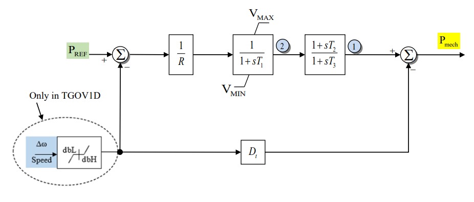
Figure 1: Governor TGOV1 model. Figure courtesy of PowerWorld
Model Parameters
Symbol |
Units |
Description |
Typical Value |
Note |
|---|---|---|---|---|
\(T_{\mathrm{rate}}\) |
[MW] |
Turbine rating |
100.0 |
|
\(R\) |
[p.u.] |
Droop Constant |
0.05 |
|
\(T_1\) |
[sec] |
Valve Time Delay |
0.5 |
|
\(T_2\) |
[sec] |
Turbine Numerator Time Constant |
2.5 |
|
\(T_3\) |
[sec] |
Turbine Delay |
7.5 |
|
\(P_v^{\max}\) |
[p.u.] |
Max Valve Position |
1 |
|
\(P_v^{\min}\) |
[p.u.] |
Min Valve Position |
0 |
|
\(D_t\) |
[p.u.] |
Turbine Damping Coefficient |
0 |
Model Variables
Internal Variables
Differential
Symbol |
Units |
Description |
Note |
|---|---|---|---|
\(P_{tx}\) |
[p.u.] |
Turbine Power (State 1 in Fig. 1) |
|
\(P_v\) |
[p.u.] |
Valve Position (State 2 in Fig. 1) |
Algebraic
Symbol |
Units |
Description |
Note |
|---|---|---|---|
\(P_m\) |
[p.u.] |
Mechnical Power to Generator |
Read by a Machine Model |
External Variables
Differential
Symbol |
Units |
Description |
Note |
|---|---|---|---|
\(\omega\) |
[p.u.] |
Machine Speed Deviation |
Read from a Machine Model |
Algebraic
Symbol |
Units |
Description |
Note |
|---|---|---|---|
\(P_{ref}\) |
[p.u.] |
Reference Power |
Either a constant parameter or external variable |
Model Equations
For readability, define:
Differential Equations
The TGOV1 differential equations, as derived from the model diagram.
CommonMath defines the Anti-Windup target and smooth approximation.
Algebraic Equations
The algebraic equation dictating the mechnical power output.
Initialization
At steady state we assume that \(P_v\) is at or within its limits. This implies the initial conditions are a function of the initial mechanical power converted to the TGOV1 component base.
And if the reference power is a constant parameter, we can determine the value by solving the steady state equations.